Home › Unlabelled ›
4 Pin Relay Diagram - Introduction of Relay - Electrical Engineering / Relays are most commonly used switching device in electronics.
4 Pin Relay Diagram - Introduction of Relay - Electrical Engineering / Relays are most commonly used switching device in electronics.. Four pin relay basic operation. 4 pin horn relay wiring installation | how to install 4pin horn harness and convert super loudly hor. Assemble all the parts as shown in the schematic diagram. 4 pin relay wiring diagram. It can be used to control various appliances and equipment with large current.
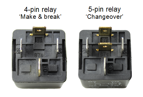
5 pin vs 4 pin wiring. Do not touch any wires that are connected to mains voltage. Let us learn how to use one in our circuits based on the requirement of our project. Understanding relays & wiring diagrams what's the difference between 4 and 5 pin relays? An iron core is surrounded by a control coil.
12V 5 Pin Relay Wiring Diagram - Wiring Diagram And ... from tops-stars.com By sending +12v between pin 1 and pin 2, you will will turn on a switch. 4 pin relay wiring diagram horn wiring schematic diagram. Normally open or normally closed. Relay schematics and diagrams there are 2 types of 4 pin relay available; Do not touch any wires that are connected to mains voltage. 4 pin relay with spst normally open contact. There may be a pin 87a, however, this is the pin that pin 30 will be connected to in the resting position, or when the control side of the relay is not energized. An iron core is surrounded by a control coil.
The six pins on the left side of the relay module connect high voltage, and the pins on the right side connect the component that requires low voltage—the arduino pins.
4 pin relay wiring diagram horn wiring schematic diagram. 65 admirable pics of bosch 4 pin re. 4 pin relay wiring diagram. In this video relay pinout function information relay testing 4 pin relay how to wire a 4 pin relay. Relay schematics and diagrams there are 2 types of 4 pin relay available; The diagram shows an inner section diagram of a relay. An iron core is surrounded by a control coil. At the initial condition when switch is open, no current flow through coil, hence common port of relay is connected to no (normally open) pin, so the lamp remain off. Normally open or normally closed. Relays are most commonly used switching device in electronics. Now, when you flip the switch, it will allow the power to flow through the switch and the coil. click the image to enlarge it. Do not touch any wires that are connected to mains voltage.
You just need to buy a separate relay harness to install it properly. 4 pin relay wiring diagram. 65 admirable pics of bosch 4 pin re. Four pin relay basic operation. 4 pin relay wiring diagram horn wiring schematic diagram.
Bosch 5 Pin Relay Diagram Wiring Diagrams Schematics With ... from i.pinimg.com Assemble all the parts as shown in the schematic diagram. New car relay wiring diagram best 5 pin bosch 4 wiring diagrams. Let us learn how to use one in our circuits based on the requirement of our project. Relays are most commonly used switching device in electronics. Normally open or normally closed. The wiring diagram is given below to help this wiring method is fully compatible with any 4 pin denso relay starting with the serial number 156700 or look like the sample denso relays below. Four pin relay basic operation. In electronics, a device is said to be a latching device if it maintains any particular fixed state even after removal of the input the the type of latch that we are using here is sr latch.
Wiring a denso relay is extremely simple.
65 admirable pics of bosch 4 pin re. Hello friends my name is. Power from relay to accessory (air horn). In this relay circuit we use a push button to trigger a 5v relay, which in turn, complete the second circuit and turn on the lamp. Do not touch any wires that are connected to mains voltage. Jvc car stereo wiring diagram. You just need to buy a separate relay harness to install it properly. In this video relay pinout function information relay testing 4 pin relay how to wire a 4 pin relay. The diagrams below are used to explain how relays work. Wiring a denso relay is extremely simple. In the circuit diagram the pin jack j1 refers to the power inputs and logic controls of the module. Smallest size (10.2 × 18.2 × 14.8 mm) at 10a switching capacity relay for high density p.c. 4 pin relay with spst normally open contact.
Relay schematics and diagrams there are 2 types of 4 pin relay available; In this video relay pinout function information relay testing 4 pin relay how to wire a 4 pin relay. click the image to enlarge it. There may be a pin 87a, however, this is the pin that pin 30 will be connected to in the resting position, or when the control side of the relay is not energized. 1a and 1c contact form available.
Automotive Relay Guide | 12 Volt Planet from www.12voltplanet.co.uk In the circuit diagram the pin jack j1 refers to the power inputs and logic controls of the module. 4 pin relay wiring diagram. 4 pin relay with spst normally open contact. In this relay circuit we use a push button to trigger a 5v relay, which in turn, complete the second circuit and turn on the lamp. Normally open or normally closed. 4 pin relay wiring diagram. You just need to buy a separate relay harness to install it properly. Assemble all the parts as shown in the schematic diagram.
65 admirable pics of bosch 4 pin re.
Four pin relay basic operation. June 3, 2019june 3, 2019. New car relay wiring diagram best 5 pin bosch 4 wiring diagrams. 1a and 1c contact form available. Relay schematics and diagrams there are 2 types of 4 pin relay available; 4 pin relay wiring diagram. 65 admirable pics of bosch 4 pin re. By sending +12v between pin 1 and pin 2, you will will turn on a switch. The six pins on the left side of the relay module connect high voltage, and the pins on the right side connect the component that requires low voltage—the arduino pins. Wiring a denso relay is extremely simple. 4 pin horn relay wiring installation | how to install 4pin horn harness and convert super loudly hor. It can be used to control various appliances and equipment with large current. Do not touch any wires that are connected to mains voltage.